First and foremost, in the previous research and projects of home automation system,
most of them are only simulated with a prototype or
model, but not implemented in a real-life application. For example,
they are using a small LED to represent as a real lamp in a
home automation system. However, the requirement of the supply power
for a small LED is different from the lamp in a real home automation
system. Therefore, battery as a power supply is not sufficient for a real-life application lamp.
Hence, we will make this project with a real-life application system.
In addition, according to our market research on existing technology,
the existing products are real-life application systems, but most of the product will only use short distance device control especially the connect from router to controller.
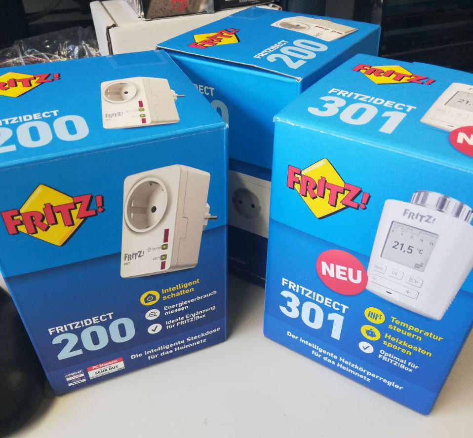
As an example, there are some home automation systems are using Digital Enhanced Cordless Telecommunication (DECT) to communicate between router and controller of devices.
Therefore, in this project, we will use Wi-Fi as a medium of communication between router and controller.
Besides, the existing products in market have less function and more expensive.
As an example, most of the products can only either switch on and
switch off the devices, but not adjust the performance of the device.
Hence, this project will be produced with more functions and the cost will be reduced compare to the existing products.
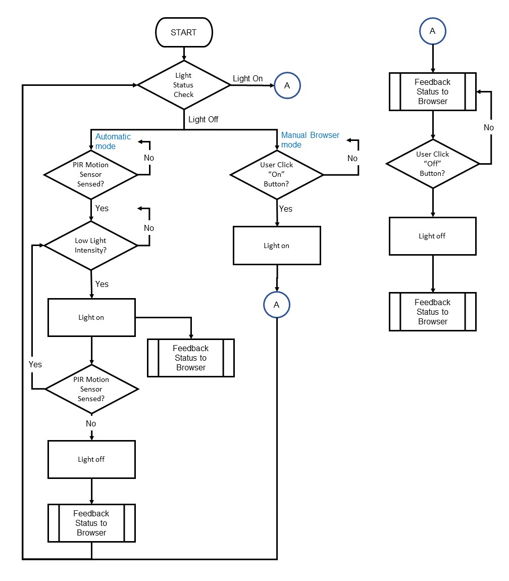
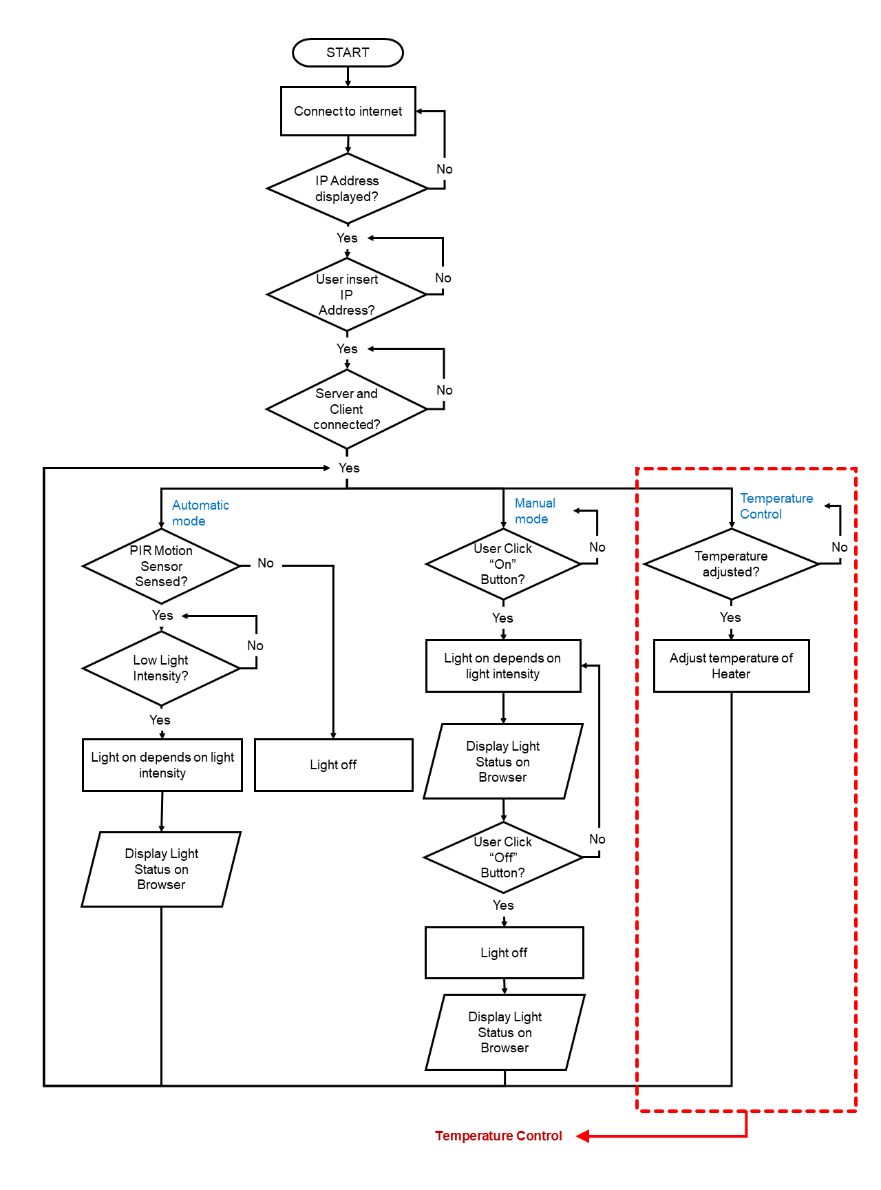
Basic Flow Chart of System
Figure 3.9.1 : This is the flow chart of the home automation control system.
Basic Concept of the System
User - Browser Manual Mode
User Action On Browser
Light Status
On Button clicked
ON
OFF Button clicked
OFF
Table 3.9.1: Manual control mode by user through Browser.
Automatic Mode
Human Motion / Presence
High Light Intensity
(Lux) in the Room
Light Status
Yes
Yes
OFF
Yes
No
ON
No
Yes
OFF
No
No
OFF
Table 3.9.2: Automatic control mode.
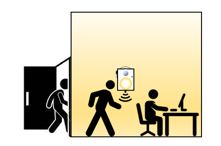
Figure 3.9.2 : When there is no motion in the room, the light will off.
Figure 3.9.3 : When there is motion in the room, the light will on.
In this project, user can control their light in their home with this system. This system is divided into 2 mode which are the automatic mode and manual mode.
Automatic mode is controlled by the PIR Motion Sensor and Light Intensity Sensor.
When the PIR Motion Sensor sensed the moving object in the room (e.g. Home Laboratory), and the light intensity in the room is very low, it will on the light.
Besides, when the light is on, it will feedback to user's browser.
If there is no any detection of motion or the light intensity of the room is high enough, then the light will off and feedback the status to web browser.
Manual mode of this system is controlled by the user through web browser.
When user click "On" button in the web browser, the light in the room will be on. Then, the system will feedback the light status to web browser.
When user click "Off" button in the web browser, the light in the room will off. After that, the system will also feedback the switched off light status to browser.
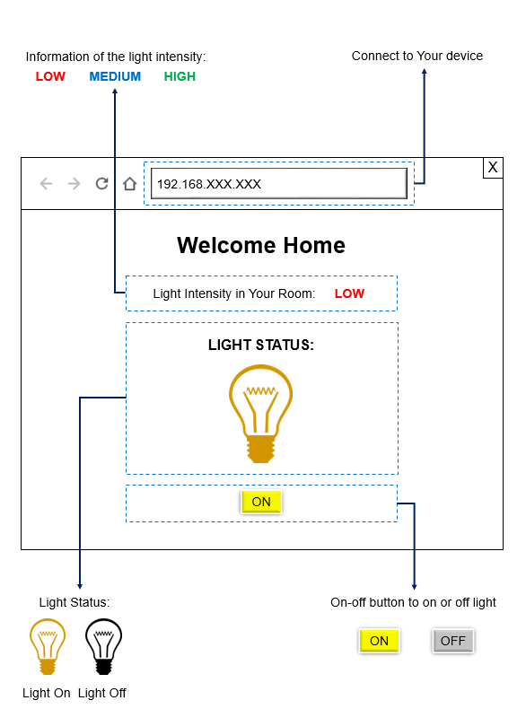
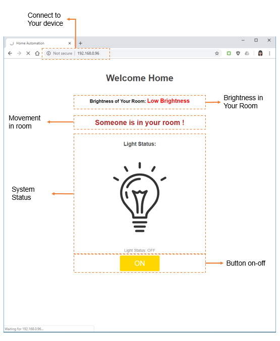
Web Interface of the System
Figure
3.9.4 : This is the idea of design for the web interface.
In this web browser interface, user can connect their system wia Wi-Fi. After user connect it to their system, user can know the light intensity in their room.
User can also know the light status whether is on or off. If the light is on, the user are not allow to click "On" button in the browser. However, if the light is off, the user can click "On" button to on the light in room.
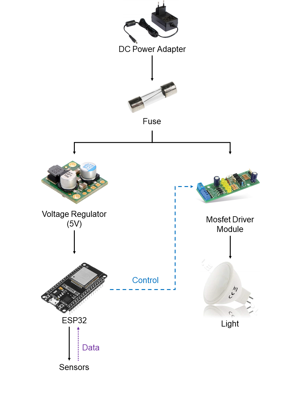
Basic Electrical Flow of the System
Figure 3.9.5 : This is the idea of the flow of electrical.
The rating of fuse that we will use in this system is
100 mA.
The calculation of the fuse rating:
Total Power Consumption = 16.925 W ≈ 17 W
Fuse Rating = (Watts / Volts) x 1.25
Fuse Rating = (17 W / 230 V) x 1.25
Fuse Rating = 92.4 mA
Therefore, we choose the next highest fuse rating to use in the
system: 100 mA.
The Ultra-compact Power Module is a small module which can supply 5V 0.6A from either 120 VAC or 230 VAC. It has environment protection and a lower power consumption with no-load loss than 0.1W.
The AC Light Dimmer Module is use to control the brightness of light in the system with the trigger from microcontroller.
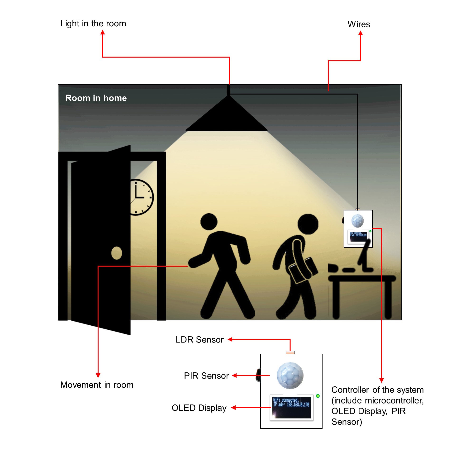
Basic Mechanical Concept of the System
Figure
3.9.6 : This is the idea of design of the system.
In this system, PIR Motion Sensor and Light Intensity Sensor will be embeded in
the controller.
Besides, there is a switch to switch on and off the whole system. This is to ensure that user will plug-in properly before they start to use it, to prevent any electric shock.
There is also a green LED to notify user that the power of this system is on.
Additional Functions
1. Temperature Control User can get the status of their home temperature with value from OLED Display which embedded in the system. Besides, user can also know the status of the room temperature from web browser.
User also can control the temperature of heater with the web browser.
Figure 3.9.7 : Flow Chart with temperature control.
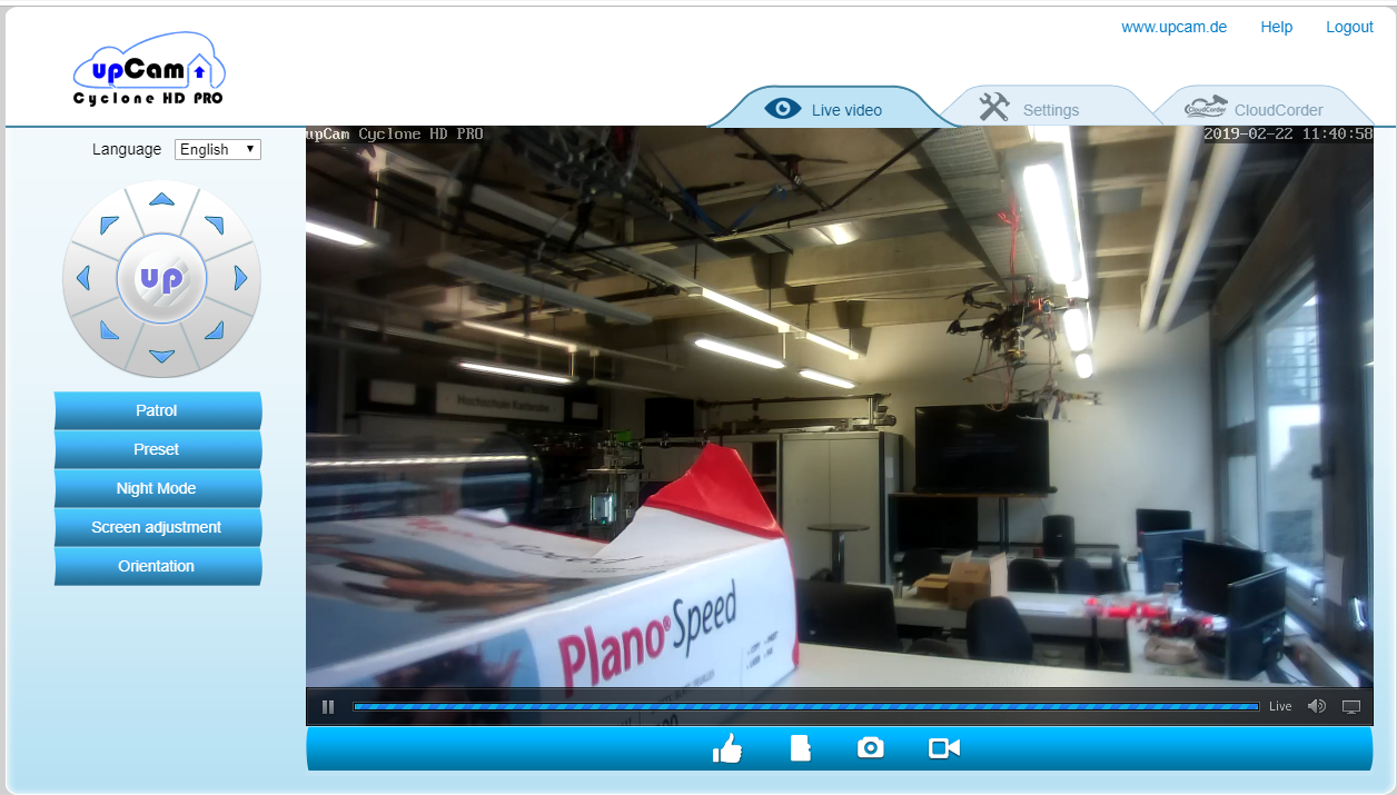
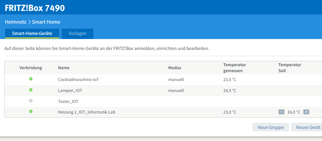
2. Combine with other existing
system. Apart from using this control system, user also can access their own home automation system through this browser.
The combination of existing system and this development system is easier for user to access all their home automation in only one browser rather than with many different Apps.
The existing systems which combined with this developed system in
web browser are MyFritz and UpCam.
Figure 3.9.8 : Additional function - upCam
Figure 3.9.9 : Additional function - MyFritz! Home Automation
Figure 3.9.10 : Additional function - MyFritz! Home Automation
Testing of the Sequence
1. Automation mode When the brightness in the home is low and there is moving object in the room, the light will turn on.
Video 3.9.1 : This is the testing of the automation mode of the system.
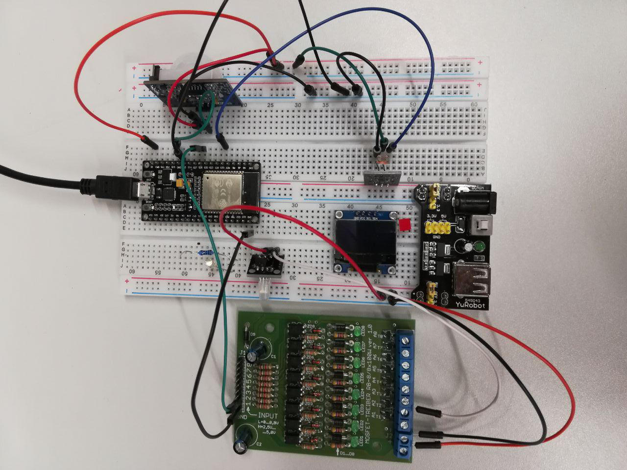
Besides, a Mosfet Driver had also been tried for this automation mode of the system.
Figure 3.9.11 :This is a testing circuit for the automation mode of the system with Mosfet Driver.
Video 3.9.2 : This is the testing of the automation mode of the system with the mosfet driver.
When the brightness in the home is low and there is moving object in the room, the light will turn on and it will feedback to browser to inform user.
Video 3.9.3 : This is the testing of the automation mode of the system with browser.
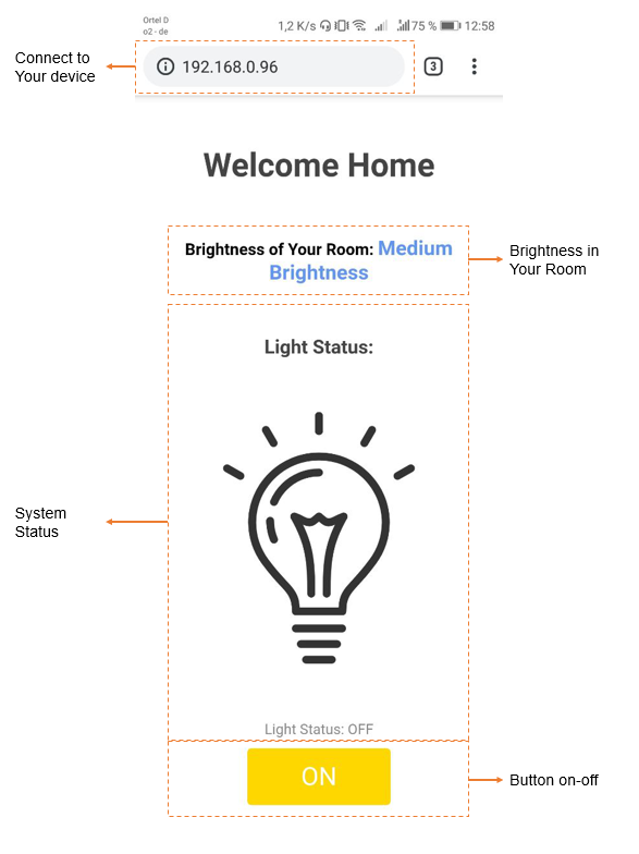
2. User-Browser Manual Mode
User can on or off their system through the Browser.User can also know their the brightness in their room.
Figure 3.9.12 : This is design for the web interface (view from phone browser),
when the light is off.
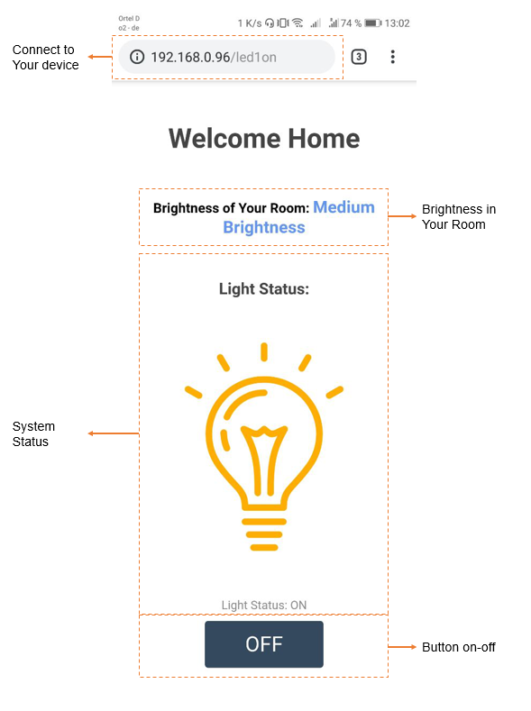
Figure 3.9.13 : This is design for the web interface
(view from phone browser), when the light is on.
Figure 3.9.14 : This is design for the web interface
(view from browser), when there is movement in room.
Video 3.9.4 : This is the testing of the user browser manual mode of the system.