|
| |
Sub- |
Solutions |
|
|
Functions |
S1 |
S2 |
S3 |
|
A |
Power supply |
AC
Plug-in |
AC Plug-in |
DC Plug-in |
| B |
Brightness detect |
LDR Sensor Module |
LDR Sensor Module |
LDR Sensor Module |
| C |
Motion detect |
PIR Sensor |
PIR Sensor |
PIR Sensor |
| D |
User react |
Web Browser |
Web Browser |
Web Browser |
| E |
Signal receive |
ESP32 |
ESP32 |
ESP32 |
| F |
Light switch |
AC
Light Dimmer Module |
AC Light Dimmer Module |
Mosfet Driver |
| G |
Data transmit |
Wi-Fi |
Wi-Fi |
Wi-Fi |
| H |
Status display |
OLED & Web Browser |
OLED & Web Browser |
OLED & Web Browser |
|
Additional Home Automation Control Function |
|
I |
Temperature detect |
DHT22 AM2302 Temperature and Humidity Sensor |
MCP9808 I2C Temperature Sensor |
DHT22 AM2302 Temperature and Humidity Sensor |
| |
|
|
|
|
Selected Solution : S1
| Description of the
solutions |
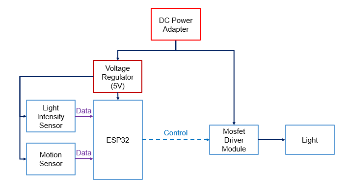
Alternative Solution S1:
This concept is a stand-alone control system which all sensors
and actuators will be combined in a device. It can be power-up by AC
plugged in. It can control the light using LDR Sensor Module and PIR
Sensor Module. This system is using AC Main Power as its power
supply and control AC Light Dimmer Module with ESP32 for the
brightness of light. However, AC Light Dimmer Module is not suitable
for fluorescent Light. Therefore, a dimmable lamp will be used in
this system.
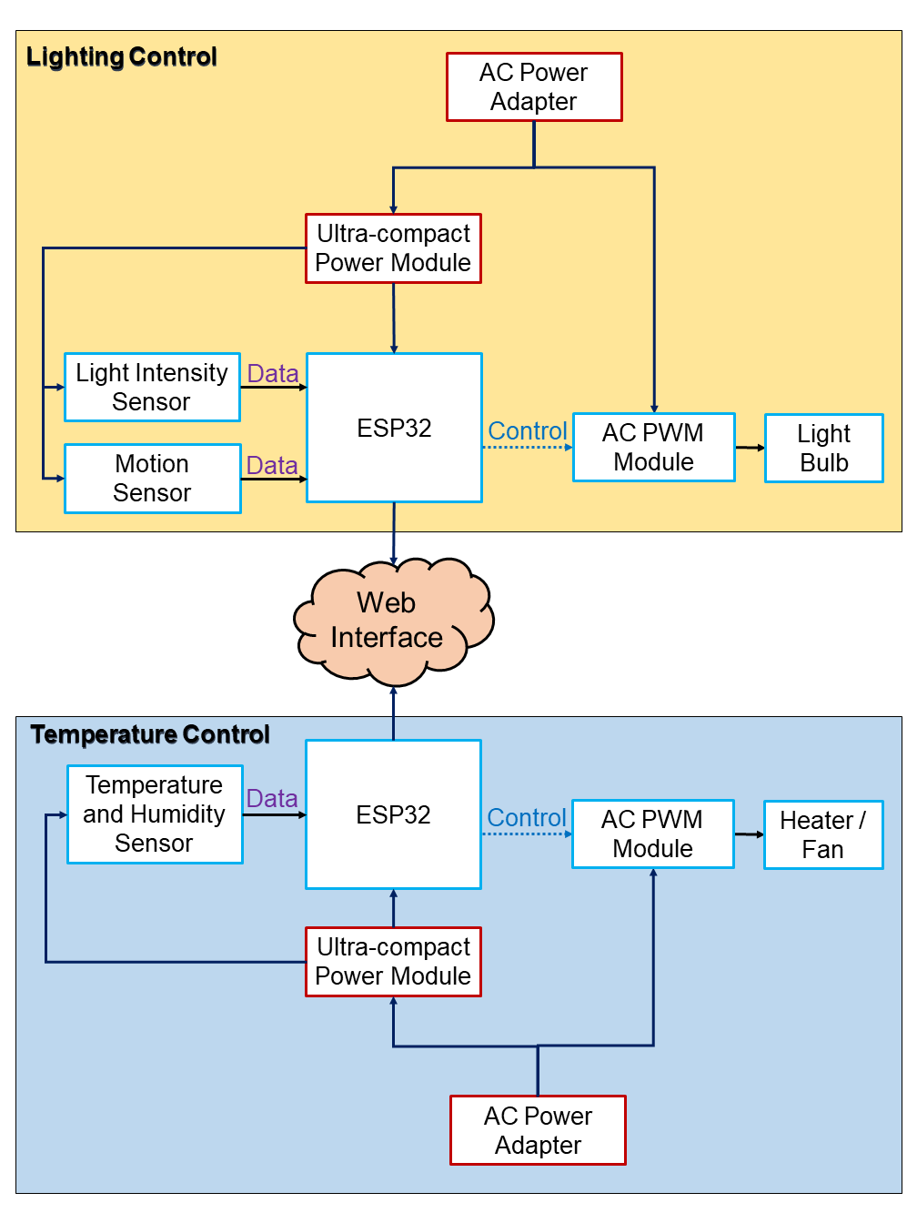
Figure 3.5.1 : System Architecture of Concept 1
Alternative Solution S2:
This concept is a system which all actuators control by only one
microcontroller and the data from all sensors will send to the microcontroller.
In this concept, controller with sensors and actuators is separated and located in
different location of a home.
Besides, in this concept, the sensors to control the system are PIR
Motion Sensor and
LDR Sensor Module. There is a disadvantage for this concept is that,
if user implement this concept, user will need to reroute the electrical cable of their home.
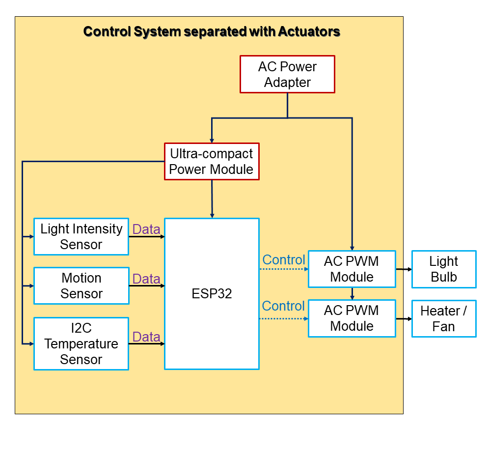
Figure 3.5.2 : Architecture System of Concept 2
Alternative Solution S3:
Concept 3 system is almost same as the system in concept 1 which
is also a stand-alone system. However, DC power supply will be used in this concept.
Besides, since it is using DC power supply, therefore the DC LED lamp bulb will be more suitable in this concept.
Apart from that, in this concept, a DC power adapter will be use to connect the system to main source and voltage regulator will concert the high DC voltage to 5V for the power supply of microcontroller.
Lastly, Mosfet Driver is being use as the driver to control the light.
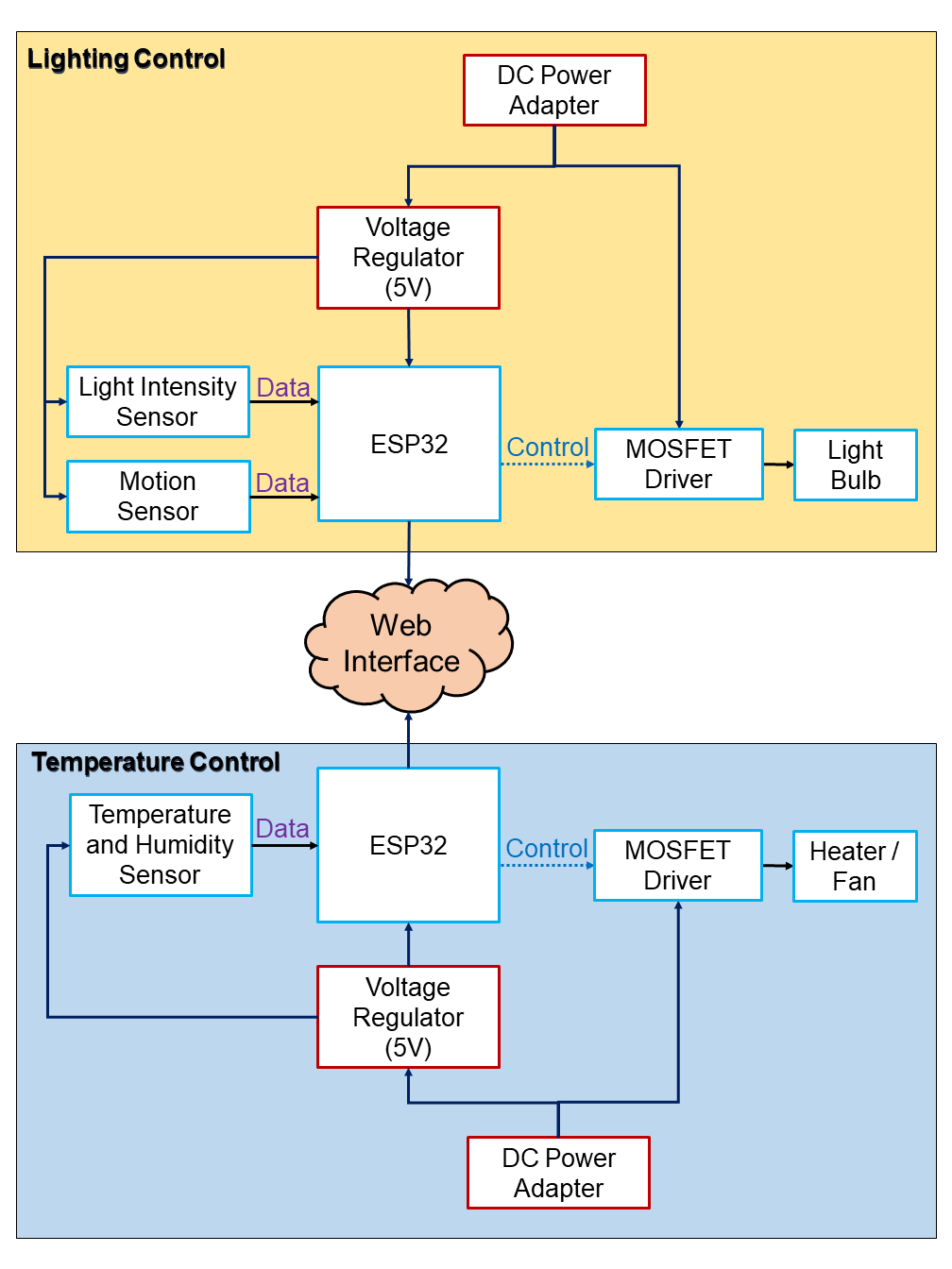
Figure 3.5.3 : Architecture System of Concept 3
|