From the existing project research, most of the project only
use model for simulation without applying in real life.
Therefore, for this project my goal is to make a real life application based on these
existing system and project. As for the product available in the
market which is used in real world, they use high technology
with very secure protection in terms of database resulting a
very high cost. Hence for this project, I want to create a
simpler smart street light system based on moving object with
lower cost. The system can be used around campus of Hochschule
Karlsruhe in order to manage the lamp around the campus area.
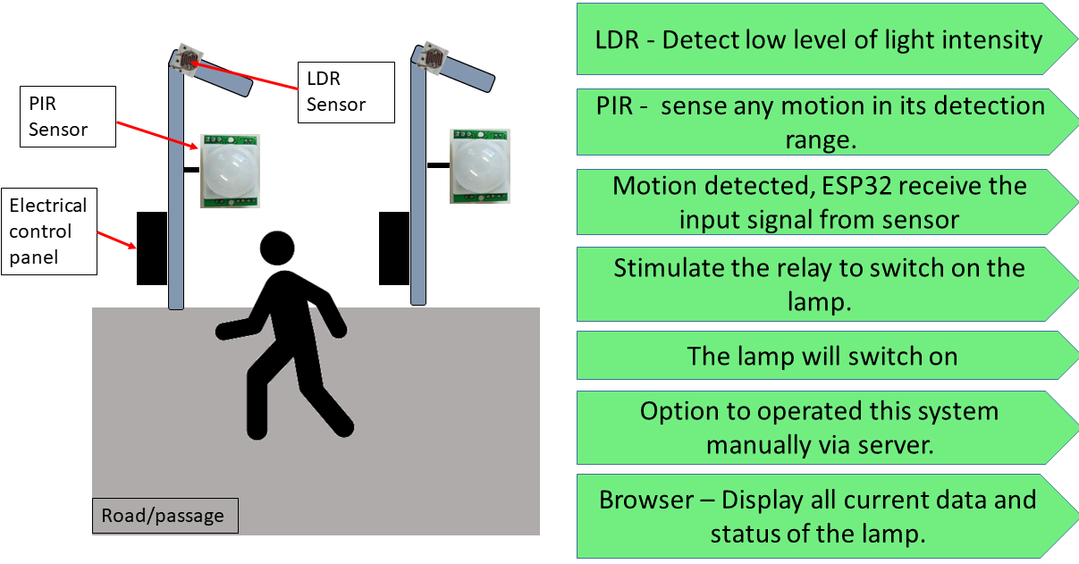
Basic concept
The basic concept of this project is when there is very
little light intensity or no light at all, LDR will allow
current pass through it and PIR sensor can sense any motion in
its detection range. If there is a motion detected, ESP32 as
microcontroller that receive the input signal from sensor will
stimulate the relay to switch on the lamp. The lamp will switch
on until the object/subject move away from the lamp. The system and status of the lamp can be
monitored and accessed everywhere from the browser that will be
connected via WiFi. Apart from automated system, there will be
an option to operated this system manually via server. Concept development:
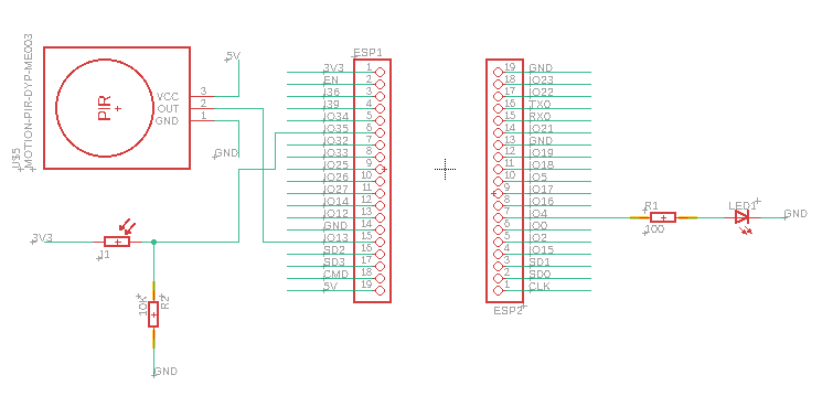
1) Separated and multiple power supply
As LED
lamp used is AC appliance, it is necessary to supply it with AC
power supply direct from the home socket. For small component
like ESP32 and sensor, since they operated in DC I want to
provide it with rechargable DC power supply which is for example using power
bank. For the model of the system, I used the basic electrical
connection as shown below. Additional component can be added
later into the circuit such as relay or MOSFET driver.
2) Web browser for
controlling and monitoring via WiFi using WebSocket
The connection between client and server can be visually
displayed on the web browser. The program should run
according to the flowchart shown below.
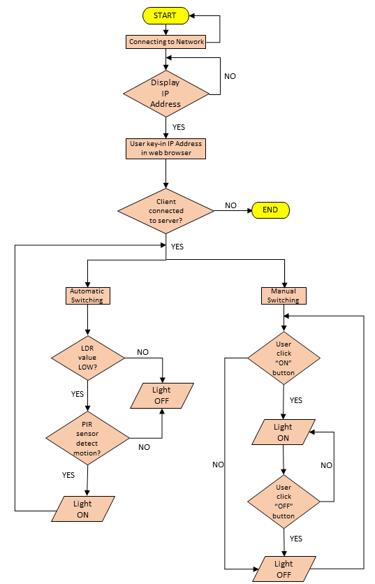 Figure 3.9.3: Flowchart
of system
Figure 3.9.3: Flowchart
of system
In the browser user can check the status of each lamp available whether it is on or off. First, user will have to enter the IP address of their device (in this case the IP address of ESP32) in order to establish communication between client and server. From the server, user can obtain data such as light intensity, presence of motion and also the lamp status. In case there is any failure detected, the lamp can also be operated manually by man via manual mode option as emergency measurement.
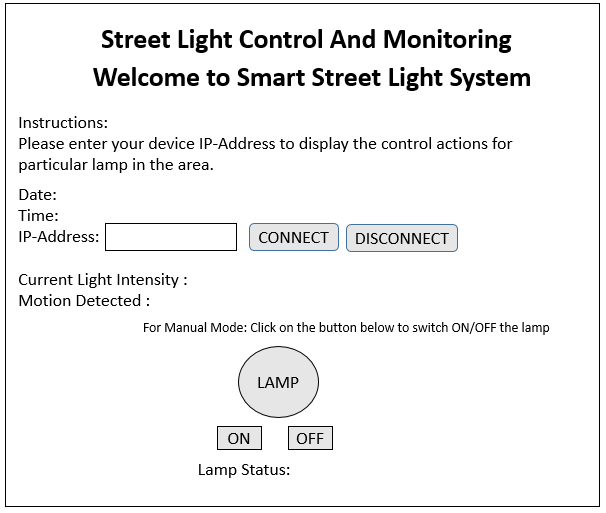 Figure 3.9.4: Sketch design of
user interface
Figure 3.9.4: Sketch design of
user interface
Web Page
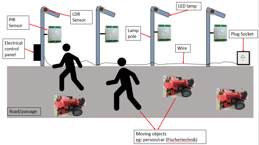
3) Mechanical
model for simulation
As a
development from existing project, I want to turn
this street lamp system into real life application.
In order to build a real life mechanical model, I need to have: - a
road/passage where the lamp poles will be installed, - LED
lamp - stand alone lamp poles that is reduced in size
compared to standard lamp stand with adjustable height: to adjust the height of the lamp pole according to size of moving objects,
- LDR and PIR sensor attach on each lamp stand, - suitable
objects as references for moving objects (Fischertechnik cars
and actual persons).
Using the above concept, there are multiple alternatives that can be considered as a solution.
Description for Alternative
Solutions
1) Alternative 1
In this concept, each lamp will has sensors
attached on it but only will be controlled by a
single microcontroller and a MOSFET driver. This
means, all the output actuators will be supplied
with voltage and current from the ESP32 itself
while the lamps will be powered on by the MOSFET
driver which get the voltage from DC supply.
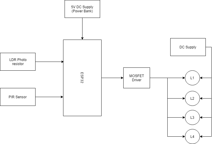 Figure 3.9.7: Block diagram for
electrical connection (Alternative 1)
Figure 3.9.7: Block diagram for
electrical connection (Alternative 1)
2)
Alternative 2
Act as a stand alone
system where each pole has their own
microcontroller that will be connected to
the router. The microcontroller will act as
a station to get internet from the router.
Each lamp is controlled by a
single MOSFET driver and also has their own
DC power
supply.
.png) Figure 3.9.8: Block
diagram for electrical connection (Alternative 2)
Figure 3.9.8: Block
diagram for electrical connection (Alternative 2)
3)
Alternative 3
Similar to
Alternative 2 but the difference is only a single
MOSFET driver will be used to controll all lamp in
which the lamp get their power supply from same DC
supply.
.png) Figure 3.9.9: Block
diagram for electrical connection (Alternative 3)
Figure 3.9.9: Block
diagram for electrical connection (Alternative 3)
Based on all these alternatives, there are
several conditions being considered upon
selecting suitable solution:
1) Enough
voltage supply and current
2) Easy to be
monitored
3) Flexible system design
4)
Costly effective
5) Able to be realized into
real application
6) Safe and reliable
(long-lasting)
Circuit
Testing
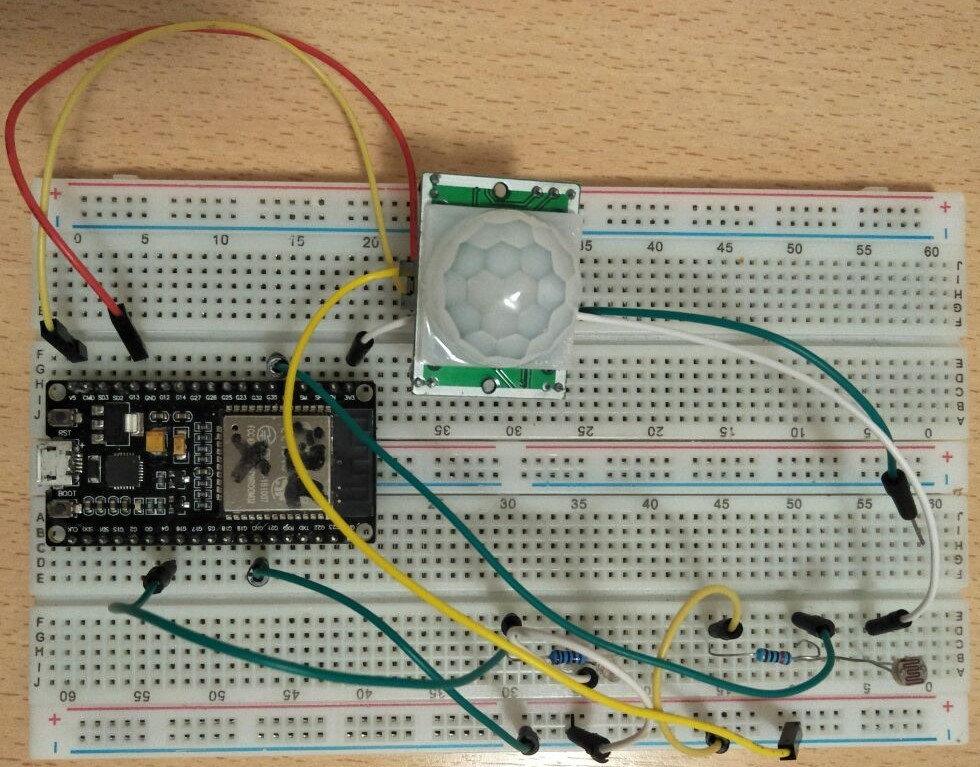
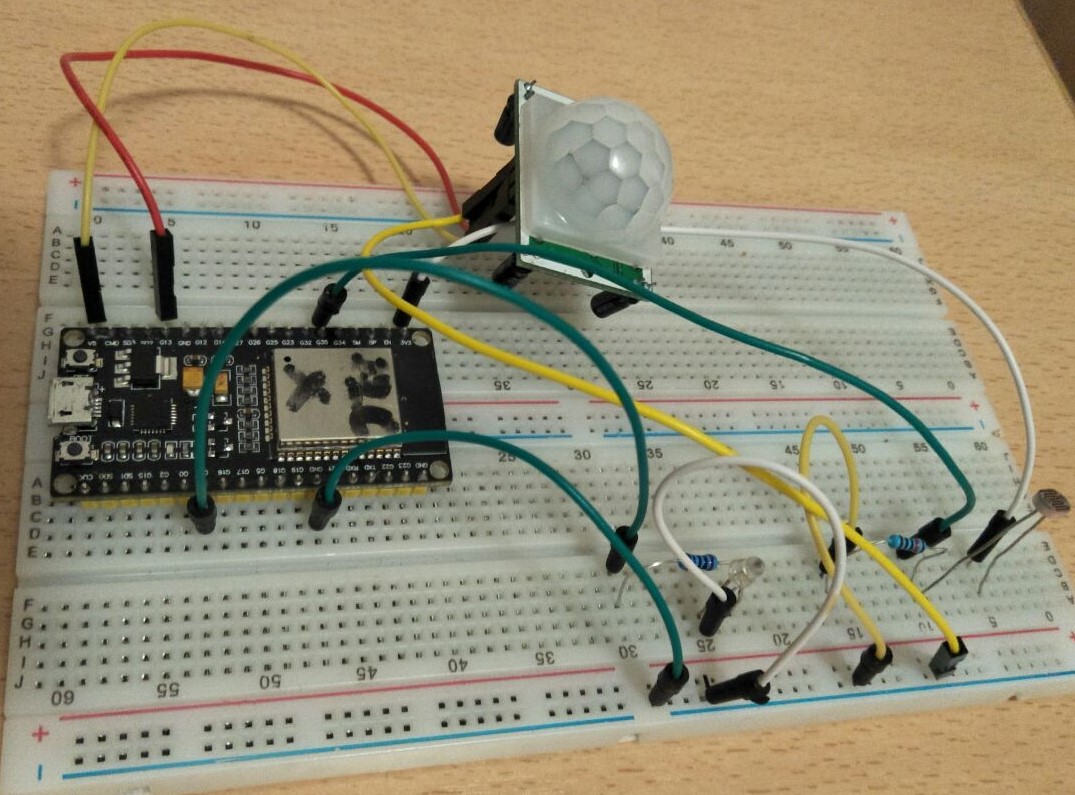
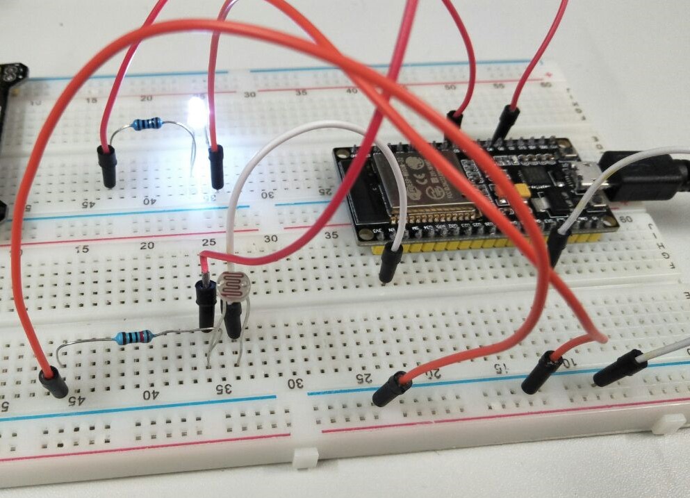
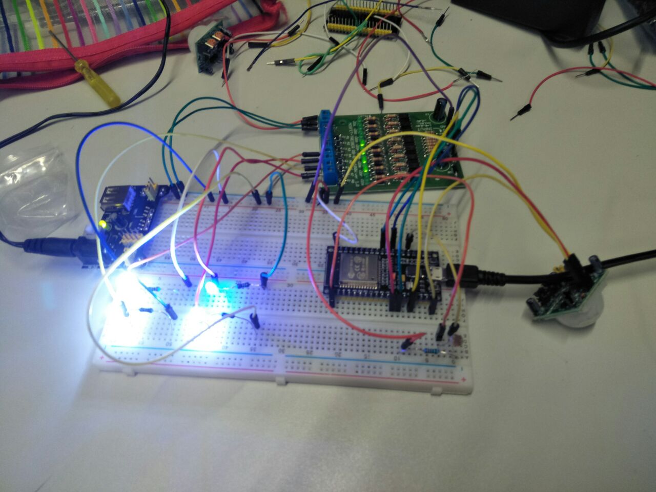
1) Basic circuit
setup consist of ESP32, an LED and also LDR.
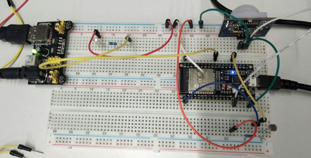
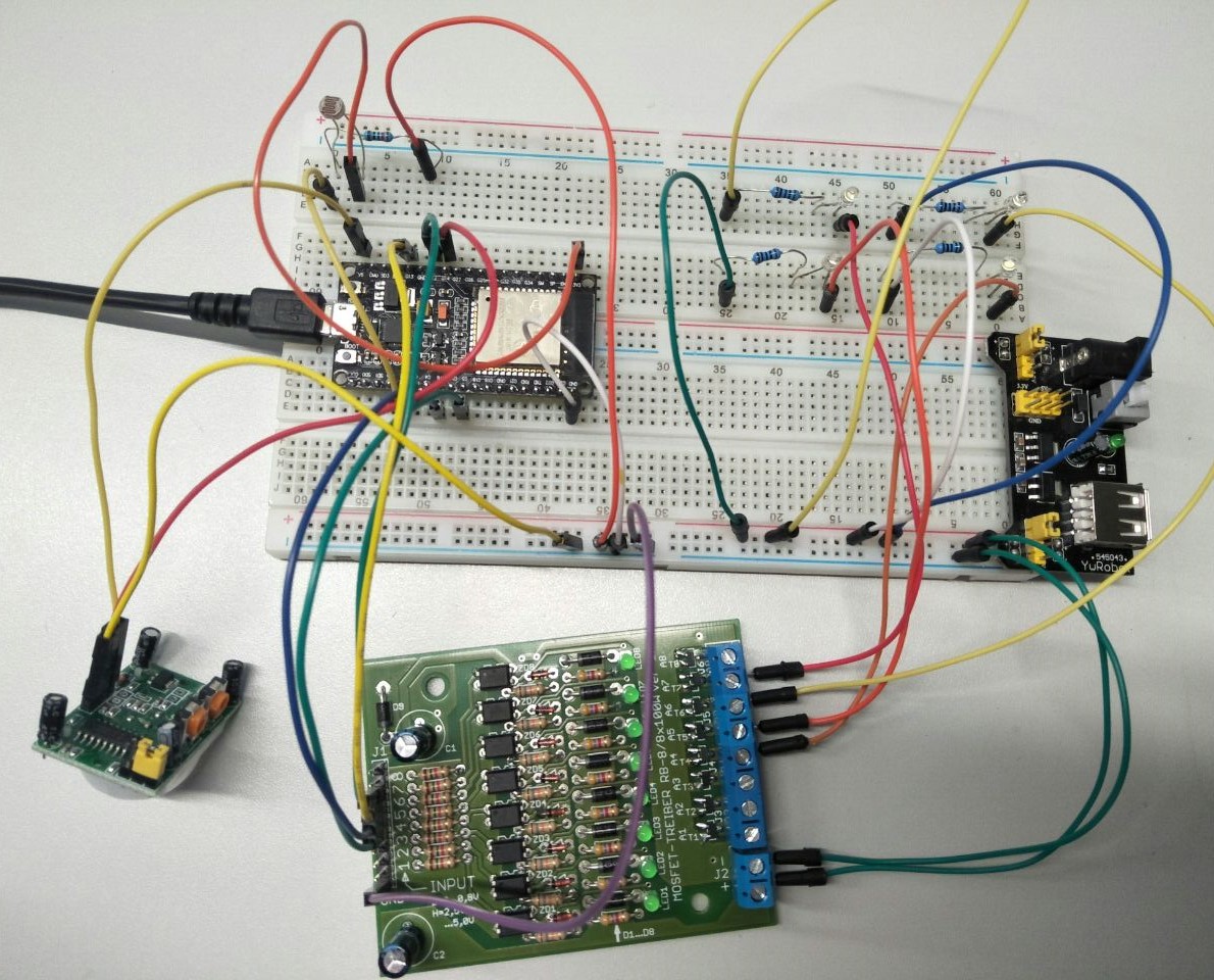
2) Circuit buildup with addition of
MOSFET driver to contol 1 LED and 4 LEDs at the same
time.
|