Links to the other sub-project-groups' website of the overall 8x8-App Project:
Link to our WebApp
Detail Functions on WebApp
The WebApp has been divided into 4 pages which are the homepage and 3 functions: Tap-to-Light, Text Generator, and Light Show and 2 sections
for every page as well. One section is the main part that user will control the pattern
that will be shown on 8x8 RGB LED whereas the another section is the setting part for the ESP32 and MQTT.
A. Homepage of the WebApp:
User able to choose the mode they wish to play. For example: Tap-To-Light, Text Generator and Light Show as well.
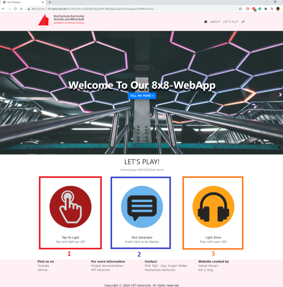
Figure 4.3.1: Homepage
1. Tap-To-Light function:
User able to control the 8x8 RGB LED by single pixel.
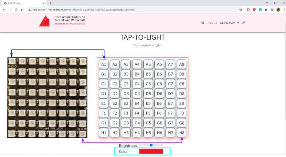
Figure 4.3.2: Tap-to-Light Page with real 8x8 RGB LED
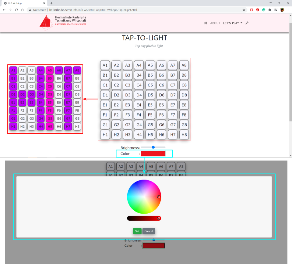
Figure 4.3.3: Tap-to-Light Page
If the button for picking color has been clicked, a color picker window will appear.
In this window, user able to choose their desired color and click 'Set' button to set the data of the color into system. User also can choose the brightness that they wish to show on LED by using the slidebar.
After user has set-up all the configurations, then user can choose their desired pixel button from A1 to H8 (which is the same concept to 8x8 matrix. For example, A1: A is the row and number 1 is the column on the 8x8 RGB LED) to show the pattern in the 8x8 RGB LED.
2. Text Generator function:
User able to control the 8x8 RGB LED by generating text.
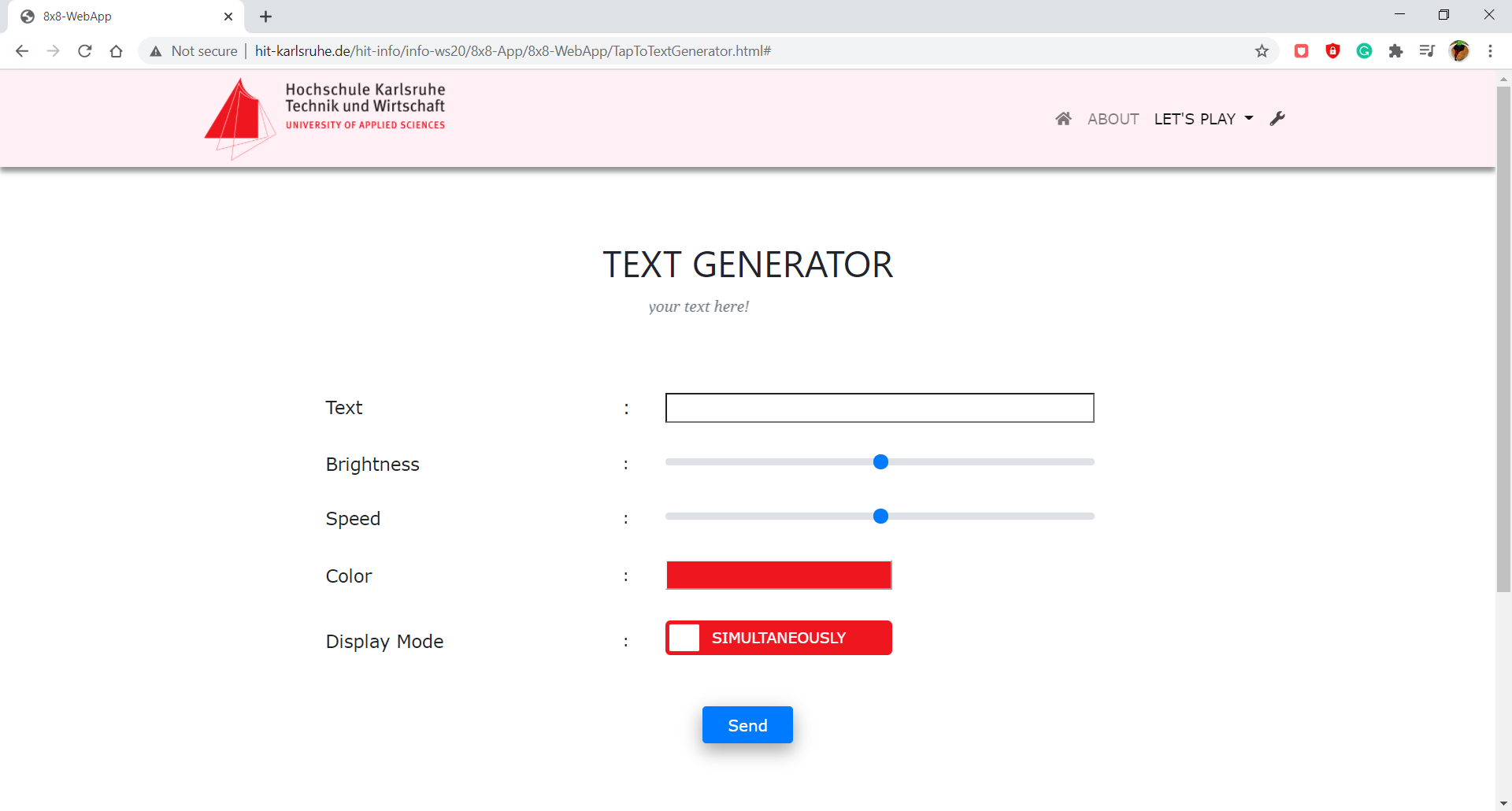
Figure 4.3.4: Text Generator Page
User required to insert the text and adjust the brightness and value of the speed, required to color and select the display mode as well.
After that user have to click 'send' button to send the command to MQTT. User able to choose the simulaneously and sequentially display mode.
Simultaneous mode is that the text will display in all the ESP sets at the same time. Sequential mode is that the text will display according to the number of ESP32 set
(with 8x8 RGB LED). This is mean that user will see the text is
moving forward (from last 8x8 RGB LED to the first one).
3. Light Show function:
User able to control the 8x8 RGB LED by all the light show.
This function is for the 16 sets of 8x8 RGB LED with ESP32.
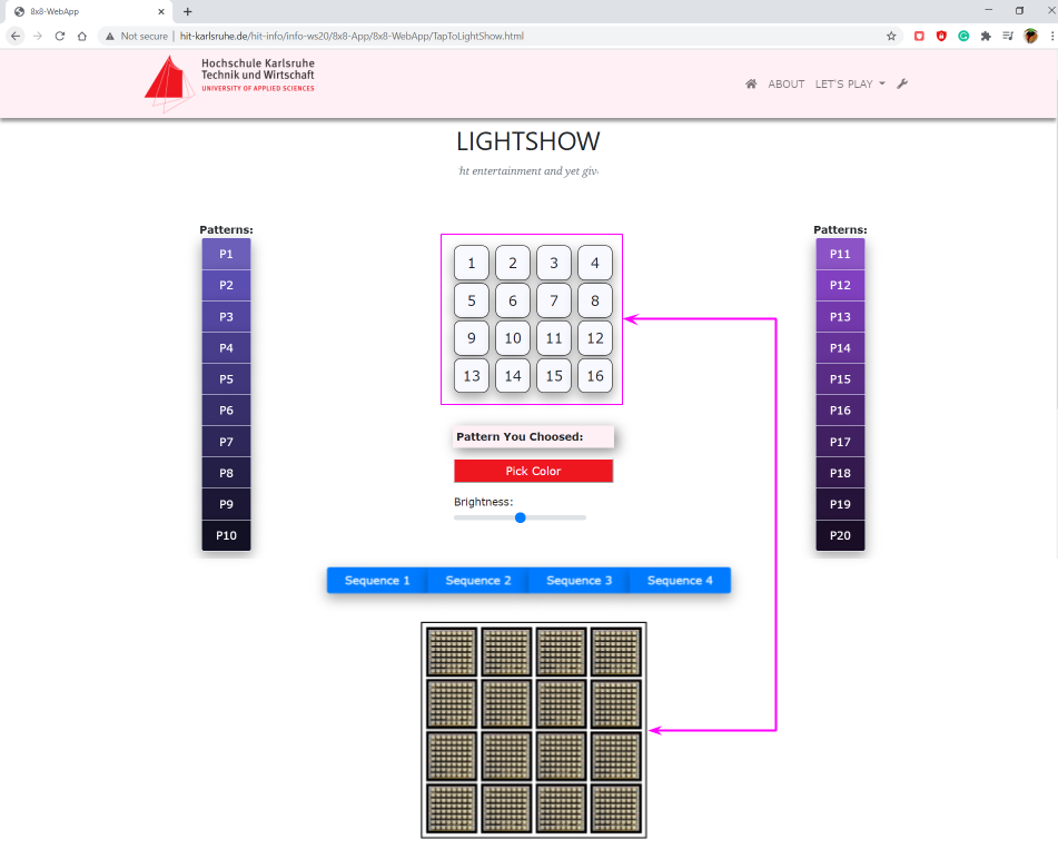
Figure 4.3.5: Light Show Page buttons compare with real view of the arrangement of 16 sets ESP32 with 8x8 RGB LED.
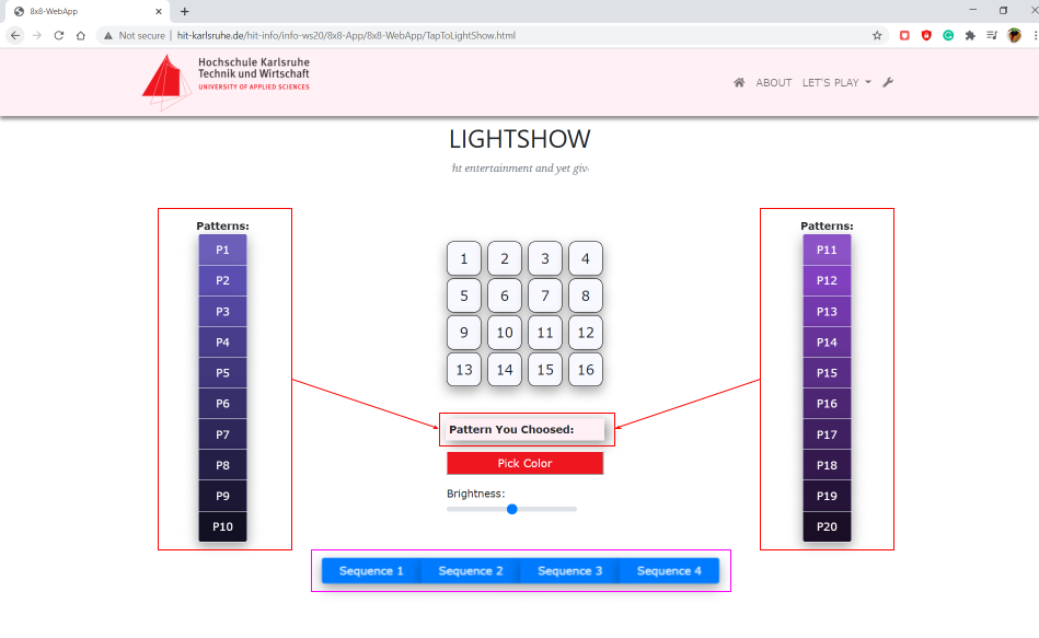
Figure 4.3.6: Light Show Page
The buttons from 1 to 16 which in the 4x4 matrix form is representing the arrangement of ESP32 sets. User required to pick the sequence from the button P1 to P20. Then user can pick their favourite color from the 'Pick Color' button and brightness from the brightness slider.
This pattern will be play by single ESP32 set.
Besides, if user play the 'Sequence' at the bottom part of this page, then all selected ESP32 will play sequentially according to the pattern selected.
B. Settings in WebApp:
User able to monitor battery status, brightness status,
ESP32 sets connection status, switched on or off of the 8x8 RGB LED set, energy optimization function,
sleep mode control and connect a specific MQTT broker and port.
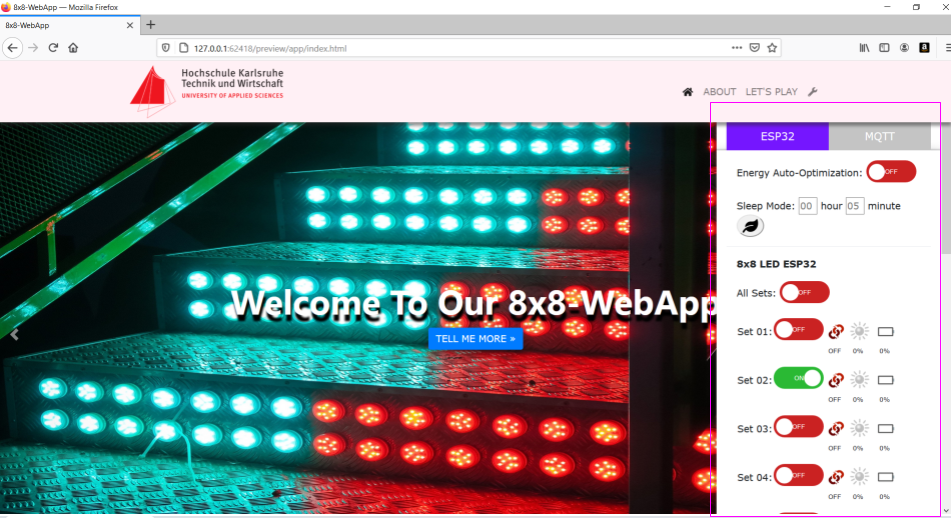
Figure 4.3.7: Settings - ESP32 Sets
In the ESP32 settings, user able to set the Energy Auto-Optimization function. This is to let ESP32 to control the brightness of the LED automatically depends on the reading from LDR sensor.
This function can save the energy from being waste and more energy efficient. Please be note that, since with this function ESP32 will automatically take control of the brightness, all brightness slidebar will be disabled.
For more energy efficient, user able set the ESP32 into sleep mode. User able to set the time to let ESP32 to wake up. After user set the time for waking up, then user need to click the sleep mode button for the WebApp to send the command to MQTT.
Apart from that, user able to choose which ESP32 should be turn on to listen the command from MQTT by clicking the toggle buttons for ESP32 sets. For example, when user toggled only the "Set02" to be on, then then user play with the functions mention above, only the set 2 will be on.
Last but not least, user able to monitor the status of MQTT connection, brightness of the surrounding and battery status as well.
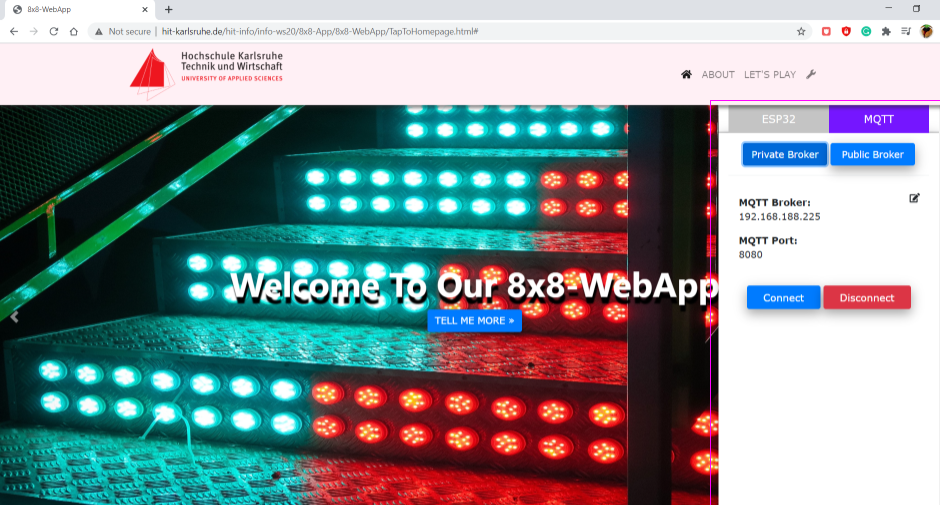
Figure 4.3.8: Settings - ESP32 MQTT Settings
In the MQTT settings, user able to set the MQTT broker and its port. In default, the data of MQTT broker and MQTT port has been set into the "Private Broker" and "Public Broker" buttons.
If user want to change the data, user can click on the edit button and set their preference as "Private Broker". Then user need to click on the "Connect" button to connect to the MQTT.
|